If you are considering performing disassembly I highly recommend to check out the HARDWARE SUPPORT LIST first to make sure that you are not disassembling a strategy that may not be needed.
Binary Files
In most cases, the only method of retrieving a clean unmodified bin is to extract the bin from the ecu. See the Getting Started write up for specifics. Tomas Tomin also offers hardware for reading ECU's, more info can be had on his FORDIAG.CZ forum. Direct link to downloading ForDiag Software HEREPadding (filler) and Bank Order
Before we can even begin to discuss the disassembly process we must first have a valid bin we can disassemble. This in itself can be extremely difficult before even beginning disassembly due to the fact that some software uses a full size bin of 64k per bank where the first 8192 bytes (0x2000 hex) of each bank is padded with null filler, whilst most software uses a non-padded bin of 56k per bank (224k 4 bank file). To fuel the fire, some software will swap banks 8 and 9 while saving the bin. This can make getting a true unaltered bin for disassembly very difficult. For reference a binary size chart is below.| Banks | Hex | bytes | KB
| 1 | 0x 8 000 | 32 768 | 32 k
| 1 | 0x E 000 | 57 344 | 56 k
| 1 | 0x10 000 | 65 536 | 64 k
| 2 | 0x16 000 | 90 112 | 88 k
| 2 | 0x1C 000 | 114 688 | 112 k
| 2 | 0x20 000 | 131 072 | 128 k
| 2 | 0x36 000 | 221 184 | 216 k
| 4 | 0x38 000 | 229 376 | 224 k
| 4 | 0x40 000 | 262 144 | 256 k
| | |||
Identify Bank Order
Bank order can easily be identified by the beginning bytes of each bank. It is often easy to search for the ascii string to quickly find it.| Bank | hex code | ascii | |
| 0 | FF,FA,27,FE,...,60,20,63 | ` c | |
| 1 | 27,FE,0C,20,... | 'ţ | |
| 8 | FF,FA,E7,... | ˙úç | |
| 9 | FF,FA,27,FE,...60,20,65,... | ` e |
Flat Memory Addressing
For reference, I have attached a quick reference table or a "cheat sheet" if you will, that will break down the memory differences between various size bin files and how to get to the actual flat addressing the binary is referencing. This table can be used to cross calculate memory addressing between the more common iterations of bank layouts and file sizing.Note: 4 Bank EEC-V 256k binaries include the RAM (usually all filler =0xFF) 4 bank bin files are truly 216k with the end of bank 1 being used for RAM.
| 256k [0-1-8-9] (TunerPro) | 224k [0-1-9-8] (BE) | 216k [0-1-9-8] | 224k [1-8-0-9] (PCMflash/Kess) | 112k [1-8] | |
| 0 2 xxx | 0 xxx | 0 xxx | 1C xxx | - | |
| 0 4 xxx | 2 xxx | 2 xxx | 1E xxx | - | |
| 0 A xxx | 8 xxx | 8 xxx | 24 xxx | - | |
| 0 C xxx | A xxx | A xxx | 26 xxx | - | |
| 0 D xxx | B xxx | B xxx | 27 xxx | - | |
| 0 E xxx | C xxx | C xxx | 28 xxx | - | |
| 0 F xxx | D xxx | D xxx | 29 xxx | - | |
| 1 2 xxx | E xxx | E xxx | 0 xxx | 0 xxx | |
| 1 3 xxx | F xxx | F xxx | 1 xxx | 1 xxx | |
| 1 4 xxx | 10 xxx | 10 xxx | 2 xxx | 2 xxx | |
| 1 5 xxx | 11 xxx | 11 xxx | 3 xxx | 3 xxx | |
| 1 7 xxx | 13 xxx | 13 xxx | 5 xxx | 5 xxx | |
| 1 8 xxx | 14 xxx | 14 xxx | 6 xxx | 6 xxx | |
| 1 B xxx | 17 xxx | 17 xxx | 9 xxx | 9 xxx | |
| 1 D xxx | 19 xxx | 19 xxx | B xxx | B xxx | |
| 1 E xxx | 1A xxx | - | C xxx | C xxx | |
| 1 F xxx | 1B xxx | - | D xxx | D xxx | |
| 2 2 xxx | 2A xxx | 28 xxx | E xxx | E xxx | |
| 2 5 xxx | 2D xxx | 2B xxx | 11 xxx | 11 xxx | |
| 2 7 xxx | 2F xxx | 2D xxx | 13 xxx | 13 xxx | |
| 2 F xxx | 37 xxx | 35 xxx | 1B xxx | 1B xxx | |
| 3 2 xxx | 1C xxx | 1A xxx | 2A xxx | - | |
| 3 3 xxx | 1D xxx | 1B xxx | 2B xxx | - | |
| 3 5 xxx | 1F xxx | 1D xxx | 2D xxx | - | |
| 3 7 xxx | 21 xxx | 1F xxx | 2F xxx | - | |
| 3 9 xxx | 23 xxx | 21 xxx | 31 xxx | - | |
| 3 C xxx | 26 xxx | 24 xxx | 34 xxx | - | |
| 3 F xxx | 29 xxx | 27 xxx | 37 xxx | - | |
SAD - Semi-Automatic Disassembler
Now that we have a valid bin its time to run it through the disassembler. For this example I will be using FBFG2 (2004 Mustang GT) and AJAQ3 (95 Ford Ranger) There's a few disassemblers out there for the Intel 8061/8065 processors but the two most used are the Bill Lawrence Disassembler that has been around since the late 90s and the much much more recent SAD - Semi Automatic Disassembler by Andy "TVRFAN". The Bill Lawrence disassembler has been updated over the years and works flawlessly. The newer SAD Disassembler does a lot of the work for you and is much easier for the beginner to use. Not only that, its updated by the author so we can simply tell him any problem we have and he's pretty good about fixing it. A+++ in my book, the less work we have to do the better!!! So to begin, create a new folder named "disassembly" just to keep everything organized. Toss your extracted stock tune in there and name your binary file stock.bin, be sure to also toss in there a shortcut to the SAD executable.SAD can be downloaded from TVRFan's GitHub HERE .
Run the Disassembler
Now is the time to run your binary through the disassembler. Simply drag and drop the bin file over the SAD executable and it will begin.
SAD - _msg.txt - Messages
First things first, open up the message file stock_msg.txt and make sure theres no major errors. Scroll on down to the 2nd rbase list toward the end of the messages file. Now click just above it and scroll back up to the top, hold down the Shift button and Press A to select all of it and press backspace, you'll now see the rbase list at the top of the msgs file in notepad. Now scroll on down to the end of the subroutine list just beaneath it and deleted everything after the end of the subroutine list. You can do a simple Ctrl + F and pop up the find type in "---" and delete the entire line that those comments are noted. Now save the file as stock_dir.txt You now have a directive file to begin tinkering.Directive File
The directive file is where you will assign labels to addresses you decode, this will make it MUCH EASIER to do disassembly since you can very easily see the PID name where a value is being used. The following is a quick cheat list of the temporary registers used in most EEC-V's. Copy and paste the following into your xxxx_dir.txt file at the top of the list just beneath the rbase parameters and before the subroutines:| SYM 24 "temp0l" |
| SYM 25 "temp0h" |
| SYM 26 "temp1l" |
| SYM 27 "temp1h" |
| SYM 28 "temp2l" |
| SYM 29 "temp2h" |
| SYM 2A "temp3l" |
| SYM 2B "temp3h" |
| SYM 2C "temp4l" |
| SYM 2D "temp4h" |
| SYM 2E "temp5l" |
| SYM 2F "temp5h" |
| SYM 30 "temp6l" |
| SYM 31 "temp6h" |
| SYM 32 "temp7l" |
| SYM 33 "temp7h" |
| SYM 34 "tmp1l" |
| SYM 35 "tmp1h" |
| SYM 36 "tmp2l" |
| SYM 37 "tmp2h" |
| SYM 38 "tmp3l" |
| SYM 39 "tmp3h" |
| SYM 3A "tmp4l" |
| SYM 3B "tmp4h" |
| SYM 3C "tmp5l" |
| SYM 3D "tmp5h" |
| SYM 3E "tmp6l" |
| SYM 3F "tmp6h" |
| SYM 40 "tmp7l" |
| SYM 41 "tmp7h" |
| SYM 42 "tmp8l" |
| SYM 43 "tmp8h" |
| SYM 44 "tmp9l" |
| SYM 45 "tmp9h" |
| SYM 46 "tmp0l" |
| SYM 47 "tmp0h" |
| SYM 48 "fgtmp0l" |
| SYM 49 "fgtmp0h" |
| SYM 4A "fgtmp1l" |
| SYM 4B "fgtmp1h" |
| SYM 4C "fgtmp2l" |
| SYM 4D "fgtmp2h" |
| SYM 4E "fgtmp3l" |
| SYM 4F "fgtmp3h" |
| SYM 50 "fgtmp4l" |
| SYM 51 "fgtmp4h" |
| SYM 52 "fgtmp5l" |
| SYM 53 "fgtmp5h" |
SAD - _lst.txt - Listing
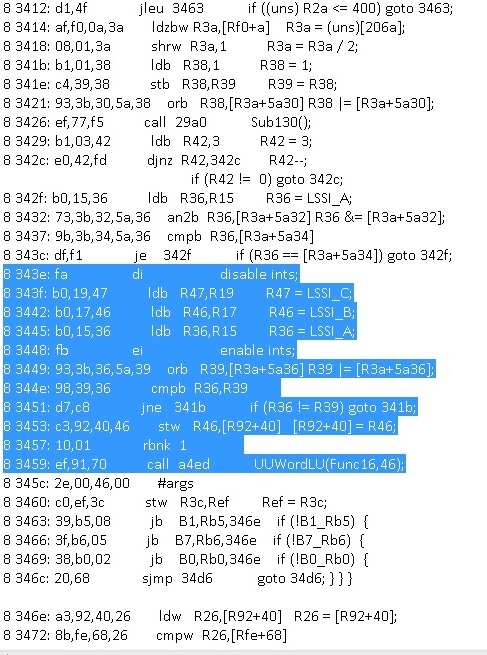
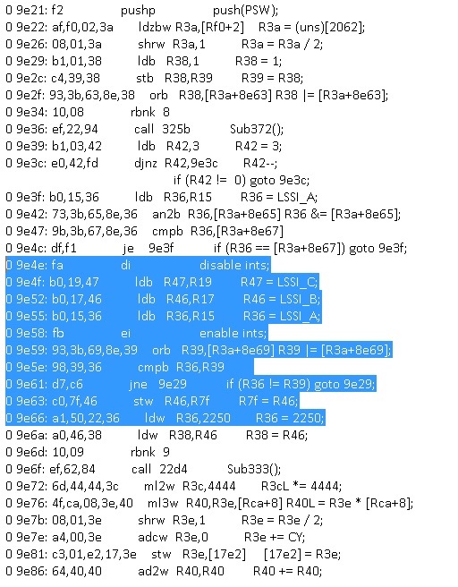
Now go back to SAD and click View >> Output File (or just open the stock_lst.txt file it created). Your disassembly listing should now be opened in notepad. At this time your probably wondering, where do I begin? Well that depends on who you ask, many start at the beginning and work their way through the code, me personally, I'm rather impatient and like to jump right to the good stuff as quickly as possible. The most important function in a Mass Air ECU is the Mass Air Flow transfer curve, so I jump straight to it :) The MAF transfer is VERY EASY to find. AFAIK, in all strategies (at least all that I've worked on) the MAF lookup code is identical. In your listing file, go up top and click on search and type in "LSSI_C". You want to keep searching until you find where interrupts have been disabled right before the LSSI is read. If it has, directly beneath LSSI_C you will see LSSI_B and LSSI_A being read as well and interrupts re-enabled. If you scroll down just below that a few operands, you will see a call to the interpolation routine.| Here is an example of the maf lookup in a 2 bank strategy | Here is an example of the maf lookup in a 4 bank strategy
Note that it is showing the outdated SAD disassembly listing. |
| 
|
Verify MAF Transfer
On 2 bank ecu's, the call will have the function number in it being called, in the example above SAD automatically named the maf transfer function "Func16", you can verify that is the actual MAF transfer by going to that function number and looking at its values. For 4 bank ecu's the lookup routine will have the maf transfer address loaded into register 36 before the call is made. You can go to that address (2250 in the example above) and verify it is correct as well. In both cases the MAF function will be 30 rows long and start with an FF FF and end with an 00 00. Congrats! you've just found the most important function in the ecu!The y axis of the maf transfer is the airmass flow. Depending on your strategy the airmass flow hex value to lbs/min of airflow equation is affected by the processor speed. The table below lists the ecu clock speeds and their typical conversion. In newer ecu's / strategies the native value is already lbs/min.
ECU Clock Speed
| MHz | XTALHPS | Units | Equation | Strategy |
| 27 | 4.0 | lbs/min | X / 1024 | RZASA FBGI0 |
| 23 | 3.0 | lbm/tick | X / 5.302409021014864 * 2.2 / 60 | CVAF1 |
| 21 | 2.0 | lbm/tick | X / 163.5670949911362 | CRAI8 |
| 18 | 1.0 | lbm/tick | - | - |
| 15 | 0.0 | lbm/tick | X / 83.75154837603146 | GUFX |
| X / 3.1562283 * 2.2 / 60 | GSALI | |||
Directive and Comments Files
Now that we know the maf transfer's address we can add that to the directive file along with the maf voltage register and name the maf and interpolation routines. In your disassembly folder where your tune is saved, right-click >> new text document, name it stock_dir.txt, while your at it create a stock_cmt.txt file as well.Directive
In your directive file, you will want to assign the maf a name so it will automatically be labelled in the code, this will make life MUCH easier. To do so, you simply open up your newly created stock_dir.txt text file with notepad and enter the following.| subr | 09e21 | "subr_MAF" |
| func | 12250 122c7 | "func_MAF_Transfer" | : | W | V | +12800 | : | W | V | +1024 |
For detailed information reference SAD.pdf for a full breakdown of the disassemblers functions.
The following quick reference charts are to quickly find the end address of a function and table to input in your directive file.
| Tbl | Y Rows | x | X Cols | Decimal Size | Hex Size | ||
| Tbl | 10 | x | 12 | byte(*2) | (120-1)= 119 | 77 | |
| Tbl | 10 | x | 10 | byte(*2) | (100-1)= 99 | 63 | |
| Tbl | 9 | x | 11 | byte(*2) | (99-1)= 98 | 62 | |
| Tbl | 8 | x | 12 | byte(*2) | (96-1)= 95 | 5F | |
| Tbl | 8 | x | 10 | byte(*2) | (80-1)= 79 | 4F | |
| Tbl | 6 | x | 12 | byte(*2) | (72-1)= 71 | 47 | |
| Tbl | 6 | x | 6 | WORD(*4) | (72-1)= 71 | 47 | |
| Tbl | 6 | x | 6 | byte(*2) | (36-1)= 35 | 23 | |
| Tbl | 5 | x | 5 | byte(*2) | (25-1)= 24 | 18 | |
| Func | Columns | Decimal Size | Hex Size | ||||||
| Func | 30 | WORD(*4) | (120-1)= 119 | 77 | |||||
| Func | 13 | WORD(*4) | (52-1)= 51 | 33 | |||||
| Func | 12 | WORD(*4) | (48-1)= 39 | 2F | |||||
| Func | 12 | byte(*2) | (24-1)= 23 | 17 | |||||
| Func | 10 | WORD(*4) | (40-1)= 39 | 27 | |||||
| Func | 10 | byte(*2) | (20-1)= 19 | 13 | |||||
| Func | 8 | WORD(*4) | (32-1)= 31 | 1F | |||||
| Func | 8 | byte(*2) | (16-1)= 15 | F | |||||
| Func | 7 | WORD(*4) | (28-1)= 27 | 1B | |||||
| Func | 7 | byte(*2) | (14-1)= 13 | D | |||||
| Func | 6 | WORD(*4) | (24-1)= 23 | 17 | |||||
| Func | 6 | byte(*2) | (12-1)= 11 | B | |||||
| Func | 5 | WORD(*4) | (20-1)= 19 | 13 | |||||
| Func | 5 | byte(*2) | (10-1)= 9 | 9 | |||||
| Func | 4 | WORD(*4) | (16-1)= 15 | F | |||||
| Func | 4 | byte(*2) | (8-1)= 7 | 7 | |||||
Comments
In your comments file, you want to put notes as to what each line of code is doing, that way you can very easily work on the code without having to decipha what you've already deciphered. This will make the process MUCH easier in the long run especially when you walk away from the code for a while and jump back in it months later. So open up your newly created stock_cmt.txt text file with notepad and enter the following.| 09e20 | |<---------------------------------> |
| 09e20 | |MAF Subroutine |
| 09e20 | |<---------------------------------> |
| 09e66 | // MAF Transfer Function |
| 12250 | // MAF Transfer Function |
Repeat
Now that you've updated the comments and directive file, re-run SAD and check out the labels you've made. You will now see that its much easier to follow the code with comments and labels instead of memory address locations. Get used to re-running the disassembler, you will be repeating the disassembler indefinitely to resolve addresses to labels to make the process much easier.Understanding Opcodes
Now that we have a segment of known code, we can go through and discuss the operation codes and what exactly the calculator "ecu" is doing. The following is a listing of the Intel 8096 opcodes adjusted for the 8061/8065 instruction set. The following data is the best known information available, there are no known publically released or available 8061/8065 instruction sets, thus the following was adapted from 8096 over the years.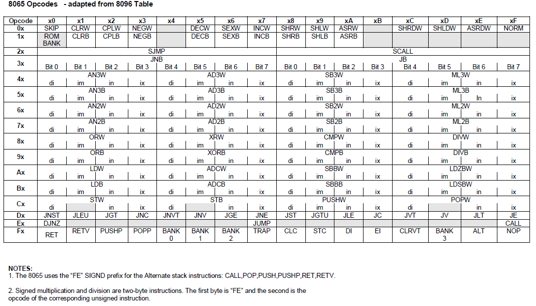
Obvious, any of the bank opcodes will not apply to single bank binaries.
The following is a very simplified list of the more common opcodes dummied down explaining what they do / how they work. It's most helpful if you are creating your own code or hacking away at the code. As you can infer, its aimed more toward the C / C++ programmers. For those not savvy in C and C++, anytime you see a bang "!" it means false / not (I.E. the result equates to ==0), any value other than 0 will return true.
| HEX | Opcode | C++ | Operation | Comments | |||||
| 00 | SKIP | jump 1 location, kin to NOP, basically a NopNop | jumps over 1 byte or "skips" the next byte, usually the following byte is a clear carry | ||||||
| 01 | reg | CLRW | reg = 0 | sets 2 bytes to 0 | clears word | ||||
| 03 | reg | NEGW | reg = -reg | inverts a word from negative to positive (signed to unsigned) | RPMDED is a perfect example where the value can be flipped so only 1 lookup is performed | ||||
| 05 | reg | DECW | reg-- | reg = reg - 1 | used to decrease a value during loops | ||||
| 07 | reg | INCW | reg++ | increases value by 1 | increments a word, 0++ = 1 not 2 | ||||
| 08 | bit | reg | SHRW | reg /= bit | 07 = / 128; 04 = /16 | bit 7 = 10000000 in binary; usually used with /10 to convert from word scaling to byte for table lookup | |||
| 09 | bit | reg | SHLW | reg *= bit | 07 = *128 |
0 0 0 0 0 0 0 0 0 0 0 0 0 0 0 1 == 1 dec 0 0 0 0 1 0 0 0 0 0 0 0 0 0 0 0 == 2048 dec; when bit shifted 11 you effectively *2048 | |||
| 0a | bit | reg | ASRW | reg /= bit | 03 = /8 | ||||
| 0c | bit | reg | SHRDW | reg /= bit | 05 = /32; 0a = /1024 0x400 | ||||
| 0d | bit | reg | SHLDW | regL *= bit | 07 = *128 | ||||
| 10 | xx | RBANK | Bank = xx | Reference Bank for next address | |||||
| 11 | reg | CLRB | reg = 0 | clears byte of data | |||||
| 17 | reg | INCB | reg++ | increments value by 1 | increments one byte | ||||
| 20 | jj | SJMP | jump forward | jump forward jj locations | E7 is a GOTO / JUMP for direct addressing | ||||
| 22 | jj | SJMP | jump forward +200 | jump forward jj locations THEN jump +200 | |||||
| 23 | jj | SJMP | jump forward +300 | jump forward jj locations THEN jump +300 | |||||
| 24 | jj | SJMP | jump back -400 | jump forward jj THEN jumpBACK -400 | |||||
| 26 | jj | SJMP | jump back -200 | jump forward jj THEN jumpBACK -200 | |||||
| 27 | jj | SJMP | jump back | jump forwards jj locations THEN jump back -100 | |||||
| 28 | jj | SCALL | call address | pushes current address to stack then jumps forwards jj | |||||
| 29 | jj | SCALL | call address +100 | does the same as 28 but then jumps +100 more | |||||
| 2a | jj | SCALL | call address +200 | "" | |||||
| 2b | jj | SCALL | call address +300 | "" | |||||
| 2f | J3 | SCALL | scall lower address -J3 | ||||||
| J3 Subtraction Addresses | |||||||||
| HEX = SUBTRACT | |||||||||
| 14 = -EC | |||||||||
| 1c = -e4 | |||||||||
| 2f = -d1 | |||||||||
| 4f = -b1 | |||||||||
| 7b = -85 | |||||||||
| 8b = -75 | |||||||||
| b2 = -4e | |||||||||
| ba = -46 | |||||||||
| c9 = -37 | |||||||||
| d4 = -2c | |||||||||
| 30 | reg | jj | JNB | if !Bit 0 | if bit0=0 then jj (up to 0x80) | signed jump, if exceeds 7F jump backwards | |||
| 31 | reg | jj | JNB | if !Bit 1 | if bit1=0 then jj (up to 0x80) | signed jump, if exceeds 7F jump backwards | |||
| 32 | reg | jj | JNB | if !Bit 2 | if bit2=0 then jj (up to 0x80) | signed jump, if exceeds 7F jump backwards | |||
| 33 | reg | jj | JNB | if !Bit 3 | if bit3=0 then jj (up to 0x80) | signed jump, if exceeds 7F jump backwards | |||
| 34 | reg | jj | JNB | if !Bit 4 | if bit4=0 then jj (up to 0x80) | signed jump, if exceeds 7F jump backwards | |||
| 35 | reg | jj | JNB | if !Bit 5 | if bit5=0 then jj (up to 0x80) | signed jump, if exceeds 7F jump backwards | |||
| 36 | reg | jj | JNB | if !Bit 6 | if bit6=0 then jj (up to 0x80) | signed jump, if exceeds 7F jump backwards | |||
| 37 | reg | jj | JNB | if !Bit 7 | if bit7=0 then jj (up to 0x80) | signed jump, if exceeds 7F jump backwards | |||
| 38 | reg | jj | JB | if Bit 0 | if bit0=1 then jj (up to 0x80) | signed jump, if exceeds 7F jump backwards | |||
| 39 | reg | jj | JB | if Bit 1 | if bit1=1 then jj (up to 0x80) | signed jump, if exceeds 7F jump backwards | |||
| 3a | reg | jj | JB | if Bit 2 | if bit2=1 then jj (up to 0x80) | signed jump, if exceeds 7F jump backwards | |||
| 3b | reg | jj | JB | if Bit 3 | if bit3=1 then jj (up to 0x80) | signed jump, if exceeds 7F jump backwards | |||
| 3c | reg | jj | JB | if Bit 4 | if bit4=1 then jj (up to 0x80) | signed jump, if exceeds 7F jump backwards | |||
| 3d | reg | jj | JB | if Bit 5 | if bit5=1 then jj (up to 0x80) | signed jump, if exceeds 7F jump backwards | |||
| 3e | reg | jj | JB | if Bit 6 | if bit6=1 then jj (up to 0x80) | signed jump, if exceeds 7F jump backwards | |||
| 3f | reg | jj | JB | if Bit 7 | if bit7=1 then jj (up to 0x80) | signed jump, if exceeds 7F jump backwards | |||
| 45 | xx | yy | reg3 | reg2 | AD3W | reg2 = [reg3 + yyxx] | |||
| 4b | ptr | of | reg2 | reg | SB3W | reg = reg2 - [ptr+of] | used to subtract a minimum from a current value | ||
| 57 | reg2 | of2 | of1 | ad | r2 | AD3B | reg2= ad + [(reg2-1) + of1of2] | used to follow up with comparison usually 0 | quick way to make sure value is greater than 0 |
| 5c | reg3 | reg2 | reg | ML3B | reg = reg2 * reg3 | used to multiply byte registers and save the result as a word | |||
| 64 | reg2 | reg | AD2W | reg += reg2 | |||||
| 65 | xx | yy | reg | AD2W | reg += yyxx | simply does addition on words | sister is 75 for byte, subtraction is the opcode 69 | ||
| 66 | reg2 | reg | AD2W | reg += [reg2] | saves the value of reg2 and then increments reg2 | ||||
| 69 | xx | yy | reg | SB2W | reg -= yyxx | subtraction for words | addition is the opcode 65 | ||
| 6d | xx | yy | reg | ML2W | reg *= yyxx | simple multiplication for words | division is the opcode 8C | ||
| 71 | hex | reg | AN2B | reg (hex)bit=false | both the current and hex bit have to be equivalent for the resulting bit to be set true, think of this as AND(1) if both bits are 1 the resulting bit is 1 | disables / turns off a bit | |||
| fe = bit 0 off | |||||||||
| fd = bit 1 off | |||||||||
| fb = bit 2 off | |||||||||
| f7 = bit 3 off | |||||||||
| ef = bit 4 off | |||||||||
| df = bit 5 off | |||||||||
| bf = bit 6 off | |||||||||
| 7f = bit 7 off | |||||||||
| 75 | hex | reg | AN2B | reg += hex | adds HEX to reg | sister is 65 for word | |||
| 7c | reg2 | reg | ML2B | reg *= reg2 | multiplies 2 bytes | used to multiply a byte by another byte register | |||
| 7d | xx | reg | ML2B | reg *= xx | simple multiplication of a byte by X value | used for simple arithmetic | |||
| 88 | reg | reg2 | CMPW | reg2, reg | compare reg, reg2 | If reg2=0, instead of R0, just 0 will be compared | |||
| 89 | xx | yy | reg | CMPW | reg, yyxx | ||||
| 8a | reg2 | reg | CMPW | reg, [reg2-1] | compare reg, to reg2-1 | instead of comparing to reg2 and reg2+ (for word) it compares to reg2- and reg2 | |||
| 8b | ptr | of | reg | CMPW | reg, [ptr+of] | ||||
| 8c | reg2 | reg | DIVW | reg = regL /= reg2 | divides a long by a word | this may not be simple division | |||
| 8d | yy | xx | reg | DIVW | reg = reg / xxyy | divides a word by a value | this is simple division | ||
| 90 | reg2 | reg | ORB | reg |= reg2 | used to OR compare 2 different bytes | ||||
| 91 | hex | reg | ORB | reg ^ HexBits | if either the current or hex bit is set, the result is a set bit ; think of this as OR1, if either bit is 1 the resulting bit is 1 | used to turn on flags and pins | |||
| 1 = bit 0 on | |||||||||
| 2 = bit 1 on | |||||||||
| 4 = bit 2 on | |||||||||
| 8 = bit 3 on | |||||||||
| 10 = bit 4 on | |||||||||
| 20 = bit 5 on | |||||||||
| 40 = bit 6 on | |||||||||
| 80 = bit 7 on | |||||||||
| 92 | [ptr] | reg | ORB | reg |= [ptr] | used to OR compare 2 different bytes | ||||
| 93 | ptr | ofs | reg | ORB | reg |= ptr+ofs | used to OR compare 2 different bytes | |||
| 94 | reg2 | reg1 | XORB | reg1 ^ reg2 | exclusive OR, think of this as a difference compare, if the bits are not equal the resulting bit is 1, if both bits are equivalent the resulting bit is 0 | changes its state and flips it back | |||
| 95 | hex | reg | XORB | reg ^ HexBits | toggles a bit | changes its state and flips it back | |||
| 97 | ptr | ofs | reg | XORB | reg = reg^[ptr+ofs] | toggles a bit | changes its state and flips it back | ||
| 98 | reg2 | reg | CMPB | (signed) | |||||
| 99 | xx | reg | CMPB | reg, xx | |||||
| 9a | R[ptr] | reg | CMPB | reg, [Rptr] | compares byte to pointer | ||||
| 9b | ptr | of | reg | CMPB | reg,[ptr+of] | reg 0 will compare to 0 | |||
| a0 | reg2 | reg | LDW | reg = reg2 | |||||
| a1 | xx | yy | reg | LDW | reg = yyxx | could be val or pointer | |||
| a2 | reg2 | reg1 | LDB | reg1 = [reg2-1]; then reg2++ | takes the value at that address, then the next loop increments reg2 | used to get to the next address in an array | |||
| a3 | ptr | of | reg | LDW | reg = [ptr+of] | special function only | 0xC3 will flip the register and address | ||
| a3 | ptr(-1) | xx | yy | reg | LDW | reg = [ptr(-1) + yyxx] | loads a RAM value to a scratch register | used to compare RAM | |
| a4 | reg2 | reg | ADCW | reg += reg2 + CY | add sum of reg2 and carry to reg | ||||
| a5 | xx | yy | reg | ADCW | reg += yyxx + CY | add sum of yyxx and carry to reg | yyxx is often set to 0000 to get carry only | ||
| ac | reg2 | reg | LDZBW | reg = reg2 | |||||
| ad | xx | reg | LDZBW | reg = xx | |||||
| b0 | reg2 | reg | reg = [reg2] (signed) | ||||||
| b1 | xx | reg | LDB | reg = xx (byte) | |||||
| b3 | 01 | xx | yy | reg | LDB | reg = [yyxx] | copies the value out that memory [address] | ||
| b3 | ptr | ofs | reg | LDB | reg = [ptr+ofs] | ||||
| b3 | ptr(-1) | ofs | 00 | reg | LDB | reg = [ptr+ofs] | loads a byte of RAM into a scratch register | used to get at an index | |
| b3 | reg2(-1) | Axx | Ayy | reg | LDB | reg = [ [reg2 + [AyyAxx]] | loads a byte of offset ram into a scratch register | used in a loop to copy a list | |
| bc | xx | reg | int | ||||||
| bd | xx | reg | LDSBW | reg = SSxx | loads a word with a signed byte, bits 8 through 15 will be filled with the value of bit 7, either all 0 or all 1's | ||||
| c0 | reg1 | reg2 | STW | reg1 = reg2 | loads value from register 2 in to register 1. Often used as (0x100 shortcut - odd byte of RAM) to copy registers over. | ||||
| c2 | ptr | xx | STW | [address++] = xx | loads xx into pointer address, not into this actual address | usually used for loops to clear data | |||
| c3 | 01 | xx | yy | reg2 | STW | [yyxx] = reg2 | used to get to the upper RAM addresses 0xF000 | 0xA3 01 will flip the operand and register | |
| c3 | ptr | of | reg2 | STW | [ptr+of] = reg2 | used to get to the lower RAM addresses 0x1000 | special function only | ||
| c3 | ptr(-1) | of | 00 | reg2 | STW | reg2 = [ptr(-1)+of] | used to save a scratch register to a RAM address | ||
| c6 | ptr | xx | STB | [address++] = xx | loads xx into pointer address, not into this actual address | usually used for loops to clear data | |||
| c7 | ptr | of | 0 | STB | [(ptr+of] = 0 | if xx==0 then no reg2 check | used to clear a ram address | ||
| c7 | ptr(-1) | of | xx | reg2 | STB | [(ptr-1)+of] = reg2 | note the ptr-1 to get lower address | ||
| c9 | xx | yy | PUSHW | yyxx | puts value of x1x2 at top of stack array | ||||
| cb | ptr | of | PUSHW | [ptr+of] | puts value at address on the top of the stack array | ||||
| cb | ptr | of | POP | [ptr+of] | removes value at the top of the stack array and saves it into the address | ||||
| d1 | jj | if <= | reciprocol is > | inverse opcode is DB | |||||
| d2 | jj | if (signed) > | reciprocol is <= | inverse opcode is DE | |||||
| d3 | jj | if < | recipricol is >= | inverse opcode is D9 | |||||
| d5 | jj | if (!overflow) | jumps if overflow==0 | ||||||
| d6 | jj | if (signed) >= | jumps if >= | inverse opcode is DA | |||||
| d7 | jj | JNE | if != | jumps if != | inverse opcode is DF | ||||
| d9 | jj | if > | recipricol is <= | inverse opcode is D3 | |||||
| da | jj | if (signed) <= | jumps if <= | inverse opcode is D6 | |||||
| db | jj | if >= | jumps if < | inverse opcode is D1 | |||||
| de | jj | if (signed) < | reciprocol is >= | inverse opcode is D2 | |||||
| df | jj | if == | jumps if == | inverse opcode is D7 | |||||
| e0 | reg | jj | reg--, if !=0, then jj, then jj-100 | decrements reg (for loop) if !=0, jump forward jj then jump back -100 | used for FOR loops | ||||
| e7 | jj | j2 | JUMP | jump jj then j2 | jumps forward jj then jumps again j2 | ||||
| ef | jj | j2 | CALL | jump forward jj then j2 | pushes current address to stack, then jumps forward jj then jumps again j2 | ||||
| f0 | RET | call stack return address | returns to the top address of the stack | ||||||
| f2 | pushp (PSW) | save PSW | saves the processor state word | used to save the PSW for fiddling with the stack (passing args) | |||||
| f3 | popp (PSW) | restore PSW | returns the processor state word back to normal | MUST be followed by a return 0xF0, this is used to restore the psw after args are passed | |||||
| f8 | clear carry | ||||||||
| fb | EI | enable interrupts | |||||||
| ff | NOP | no output | jump self (do nothing), kin to SKIP | burns a clock tic, useful for accurate repetitve timing | |||||
J2 Jump Addresses
| 9c | = | -6400 | |
| 96 | = | -6a00 | |
| 97 | = | -6900 | |
| 88 | = | -7800 | |
| a1 | = | -5f00 | |
| a6 | = | -5a00 | |
| ba | = | -4600 | |
| cb | = | -3500 | |
| ef | = | -1100 | |
| f0 | = | -1000 | |
| f1 | = | -f00 | |
| f2 | = | -e00 | |
| f3 | = | -d00 | |
| f9 | = | -700 | |
| fa | = | -600 | |
| fe | = | -200 | |
| ff | = | -100 | |
| 00 | = | +0 | |
| 01 | = | +100 | |
| 02 | = | +200 | |
| 04 | = | +400 | |
| 06 | = | +600 | |
| 07 | = | +700 | |
| 09 | = | +900 | |
| 0b | = | +b00 | |
| 0d | = | +d00 | |
| 0f | = | +f00 | |
| 15 | = | +1500 | |
| 3b | = | +3b00 | |
| 46 | = | +4600 | |
| 54 | = | +5400 | |
| 5f | = | +5f00 | |
| 64 | = | +6400 | |
| 65 | = | +6500 | |
Note: Jumps are words that roll over within the same bank, a jump to 1XXXX will result in the 1 being omitted.
2's Complement Math
To understand bits, you need to understand how a byte is structured. A byte is a single register of data with a value from 0-255. A byte consists of 8 bits which is 8 "switches" in binary being that in binary you only have a value of 1 or 0, I.E. switch on (1) or off (0), or true (1) or false (0). 2s complement math can easily be broken down by understand the bits position and value. In a byte, the lowest bit (right most - bit 0) has a multiplier of 1. The first bit has a multiplier of 2, the 2nd bit a multiplier of 4, the 3rd bit a multiplier of 8, the fourth bit a multiplier of 16, the fifth bit a multiplier of 32, the sixth bit a multiplier of 64 and the final seventh bit a multiplier of 128.So to break this down, we can do a few examples to make it easier to understand.
| Binary | = | b7 | b6 | b5 | b4 | b3 | b2 | b1 | b0 | = | decimal | |
| 00000000 | = | 0 | +0 | +0 | +0 | +0 | +0 | +0 | +0 | = | 0 | |
| 00000001 | = | 0 | +0 | +0 | +0 | +0 | +0 | +0 | +1 | = | 1 | |
| 00000010 | = | 0 | +0 | +0 | +0 | +0 | +0 | +2 | +0 | = | 2 | |
| 00000011 | = | 0 | +0 | +0 | +0 | +0 | +0 | +2 | +1 | = | 3 | |
| 00000100 | = | 0 | +0 | +0 | +0 | +0 | +4 | +0 | +0 | = | 4 | |
| 00000101 | = | 0 | +0 | +0 | +0 | +0 | +1 | +0 | +1 | = | 5 | |
| 00001000 | = | 0 | +0 | +0 | +0 | +8 | +0 | +0 | +0 | = | 8 | |
| 00010000 | = | 0 | +0 | +0 | +16 | +0 | +0 | +0 | +0 | = | 16 | |
| 00100000 | = | 0 | +0 | +32 | +0 | +0 | +0 | +0 | +0 | = | 32 | |
| 01000000 | = | 0 | +64 | +0 | +0 | +0 | +0 | +0 | +0 | = | 64 | |
| 10000000 | = | 128 | +0 | +0 | +0 | +0 | +0 | +0 | +0 | = | 128 | |
| 11111111 | = | 128 | +64 | +32 | +16 | +8 | +4 | +2 | +1 | = | 255 |
Subroutine / Function Arguments
Some operations in the ecu such as doing interpolation look up or setting fault codes are very redundant, and to prevent an excessive amount of functions to do the same task, the ecu passes arguments to a function so it can carry out the task. Think of it as being variables modifying variables. In the RZAS0 binary there are only 3 functions that accepts these variable of variables "arguments". To define arguments in your directive file, simply go to the function or subroutine address and add : Y O +2 or : Y O +6. The # defines how many bytes are omitted after the function call and not used as code, that way the disassembler doesn't try to disassemble it. At this point, its not important whether the arguments are words or bytes, whats most important is that the disassembler can decipher code from arguments so you get a clean listing. For example in cbaza, you would have the following line in your directive filesubr 0717c "subr_717c" : Y O +4
which tells the disassembler anytime 0x717c subroutine is called to omit the followig 4 bytes since they are arguments and not code.
Definition File (TunerPro XDF Files)
A definition file is basically the same across all software. It maps the memory locations to human readable values. In order to add a parameter to your definition file there are a minimum of 6 values you will need to know.| PID | good to have but a good name will suffice if need be |
| Address | |
| Byte / Word | byte (1 byte = =8 bits) or word (2 bytes == 16 bits) |
| Signed / Unsigned | signed allows negative numbers |
| Equation | for example: x/2 |
| Input/Unit | Load, ECT, ACT, VSBAR, etc.. |
| Comments | Always good to describe what the paramter does. |
Categories / Levels (TunerPro XDF Header Info >> Categories)
I have found the following MAIN categories to be most effective for all parameters to fall under.Note: See the latest RZASA xdf for the most up-to-date information.
| VE Model |
| Fueling |
| ISC Control |
| Ignition |
| Components |
| H/W Configuration |
| Transmission |
| Emulation |
| ETC |
| VCT |
VID Block
The VID block is typically stored in the same location on all binaries. The VID block should be added to your definition file to give you full access.| Parameter | 128k | 256k | Equation | Comments |
| CAL_ID | FF06 | 3xFF06 | ASCII | the strategy and two letter calibration identification |
| PATS_CODE | FF13 | 3xFF13 | HEX | the unique vehicle specific pats code |
| TAG | FF63 | 3xFF63 | ASCII | TAG - contains ford copyright info such as year |
| VIN | FF80 | 3xFF80 | ASCII | VIN - used for emissions testing and by some OBD-II scanners for vehicle info |
| VID_ENABLESW | 3xFF95 | X | 42 (0xA2) == VID block enabled, 255 (0xFF) == VID Block disabled | |
| VID_REVMILE | 3xFF9A | X | vehicle tire revolutions per mile for information only, not used in any calcs | |
| VID_RT_AXLE | 3xFF9C | X/1024 | rear end gear ratio used for vehicle speed calc when the vid gear axle ratio switch is enabled | |
Important Addresses
These addresses are typical in most all 4 bank ecu's.| Address | PID | COMMENTS |
| 1x2004 | ROM_TO | checksum |
| 1x200A | BIN_CHIP_ID | calibation id |
| 1x2062 | AICE_VERS | |
| 1x2063 | AICE_SETR1_B | |
| 1x2064 | AICE_SETR1_C | |
| 1x2065 | AICE_SETR1_D | |
| 1x2066 | AICE_VRS_VAL | |
Quick Find Code Blocks
The EEC's use the same code with tidbits of code added and removed over the years, this is what causes the different strategy names. Below is a quick reference chart of common code in most eec-v ecu's. This can be used as a cheat menu to quickly find segments of code your looking for specifically. This will be aimed more toward locatings payloads but it applies for calibration constants as well.| PID | HEX SEARCH STRING | RZASA Addy / COMMENTS |
| ATMR1_HI_RES | b0,3c,c4 | |
| IPSIBR | b1,ff,34 | |
| ECT | 69,64,00,46 | |
| ACT | 64,36,40 | |
| SAFTOT | ||
| LOAD_FG | ||
| N | 79,04,3c | |
| PERLOAD | 88,28,26 | |
| TP_REL | ||
| TOTLDST | 64,42,26 | |
| IMAF | ||
| VBAT_WORD | 8c,36,3c | 0xBCF2 |
| DPFE | ||
| LAMBSE1 | b1,80,2d | |
| KAMRF1 | 80,00,44 | or 65,80,00,44 |
| IEGO1 | ||
| DASPOT | ||
| ISCDTY | a0,3c,40 | |
| VSBART_RT | ||
| BCSDC | a0,06,36 | |
| SUBR_CONSOLE_CALL | 99,f2,34 | USED ABOVE FOR DATALOGGING PATCH |
| DASPTK | 44,3c,42,2c | |
| SARCHG | 0c,01,48 | MAKE SUR YOU UPDATED THE NUMCYL REFERENCE ADDRESS!!! |
| Dashpot Decay FN879 | 68,3c,2c | all dashpot in routine |
| XTALHPS | 71,03,3f | 9x30DD |
| UPDISC | UPDATM in following routine | |
| P1000 | ||
| EGRHP | ||
| TQM_SW | Gear Axle Ratio and Rev Mile to follow | |
| Crank_PW_Mult | b1,00,3a | |
| Pump_Voltage | ad,09,38 | RFS routine |
| OL_Delay | 19,04,36 | |
| TP_OL_Threshold | : 01,3e | |
| FN1036 | a0,3c,26 | |
| FN1037 | a1,00,09,36 | |
| [code] JUMP_FRAC | 7c,35,34 | byte in code |
| [code] xx | 09,04,30 | CL idle modulation |
| [code] JUMP_MULT | 08,02,38 | |
| Slopes | 6e,ca,38 | |
| Offset | c0,2e,42 | |
| deltap | a1,00,40,26 | |
| tc_under | 71,ef,34 | psibrn/m,etc... |
| WOT_Thres | a0,27,46 | |
| fn012 | a0,37,46 | mbt routine |
| hsf | 91,40,a1 | fan values |
| crank pw | b1,00,3a | 3rd or 4th from top, can find lambse values and a great many functions!!! |
| P1000 | 37,2a,03 | mil sw and force good code |
Checksum
The ecu calculates the checksum to verify the ROM is not corrupt. To calculate the checksum the following addresses are summed up, if their value equals 0, then the checksum is valid.Side note: The actual address the checksum is saved to is null since a correct checksum will return 0.
I recommend rewriting the checksum calc routine to include the higher range on older 4 bank strategies instead of cross calculating.
| Strategy | Bank 0 | Bank 1 | Bank 8 | Bank 9 | ROM_TO |
| 4-BANK (newer) | 2000 - FFFF | 12000 - 1DFFF | 22000 - 2FFFF | 32000 - 3FEFF | 12004 |
| 4-BANK (older) | 2000 - FFFF | 12000 - 19FFF | 22000 - 2FFFF | 32000 - 3FEFF | 12004 |
| CDAN4 | 2000 - FEFF | 12000 - 1FFFF | 1200A | ||
| CBAZA | 2000 - FFFD | 200A | |||
| GUFB | 2000 - 9FFF | 200A |
TunerPro Checksum Calc
TunerPro will apply the checksum calcs STARTING with the FIRST ENTERED and working in order to the LAST ENTERED. The order they are added to the xdf is most important as the order they are displayed is not the order they are executed!!! Keep this in mind as you must ALWAYS enter in your checksum calcs in the correct order otherwise it will not function correctly.Special Instructions
Special instructions include any background manipulation you need to complete to correctly calculate the checksum.
These must be performed first (ENTERED FIRST) otherwise they will incorrectly excuted after the checksum has been calculated.
- Single Bank Special Instructions
Since the single banks tunes will calculate the checksum and save, the effect will be an alternating 0 and checksum value when saving a bin with a correct checksum already present. Thus, I recommend the following to ensure the checksum is calculated correctly 100% of the time.
Note: 0x2005 (0x0005) usually has a value of 0x00 in most all EEC-IV binaries, you must first verify.Title Start End Save Size Calc CLR_ROM_TO_A 2005 2005 200A 1-byte SUM CLR_ROM_TO_B 2005 2005 200B 1-byte SUM - 2-Bank Special Instructions
If you need to perform any special instructions on 2-bank binaries, 1x2005 usually contains 0xFF, you must verify - 4-Bank Special Instructions
If you need to perform any special instructions on 4-bank binaries, cross reference the above.
| Title | Start | End | Store | Store Size | Data Size | LSB | Plug-in | Calc | Comments | ||||||||||||||||||||||||||||||||||||||||||||||||||||||||||||||||||||||||||||||||||||||||||||||||||||||||||||||||||||||||||||||||||||||||||||||||||||||||||||||||||||||||||||||||||||||||||||||
| XX ---> | | Enter any Special Instructions first
| SumBank0 | 2000 | FFFF | 3FFF0 | 2 | 2 | LSB | Default | TWOs | Sum of bank 0
| SumBank1 | 12000 | 1DFFF | 3FFF2 | 2 | 2 | LSB | Default | TWOs | Sum of Bank 1; Older Strats may only check up to 19FFF
| SumBank8 | 22000 | 2FFFF | 3FFF4 | 2 | 2 | LSB | Default | TWOs | Sum of Bank 8
| SumBank9 | 32000 | 3FEFF | 3FFF6 | 2 | 2 | LSB | Default | TWOs | Sum of Bank 9
| SumErr | 3FFF0 | 3FFF7 | 3FFF8 | 2 | 2 | LSB | Default | Sum | Sum of All Banks
| SumOld | 12004 | 12005 | 3FFFA | 2 | 2 | LSB | Default | Sum | Copy old checksum
| Checksum_ROM | 3FFF8 | 3FFFB | 12004 | 2 | 2 | LSB | Default | Sum | Save New Checksum to ROM
| CleanupB | 32000 | 32000 | 3FFFB | 1 | 1 | LSB | Default | Sum | Set Null filler back to FF==null
| CleanupA | 32000 | 32000 | 3FFFA | 1 | 1 | LSB | Default | Sum | Set Null filler back to FF==null
| Cleanup9 | 32000 | 32000 | 3FFF9 | 1 | 1 | LSB | Default | Sum | Set Null filler back to FF==null
| Cleanup8 | 32000 | 32000 | 3FFF8 | 1 | 1 | LSB | Default | Sum | Set Null filler back to FF==null
| Cleanup7 | 32000 | 32000 | 3FFF7 | 1 | 1 | LSB | Default | Sum | Set Null filler back to FF==null
| Cleanup6 | 32000 | 32000 | 3FFF6 | 1 | 1 | LSB | Default | Sum | Set Null filler back to FF==null
| Cleanup5 | 32000 | 32000 | 3FFF5 | 1 | 1 | LSB | Default | Sum | Set Null filler back to FF==null
| Cleanup4 | 32000 | 32000 | 3FFF4 | 1 | 1 | LSB | Default | Sum | Set Null filler back to FF==null
| Cleanup3 | 32000 | 32000 | 3FFF3 | 1 | 1 | LSB | Default | Sum | Set Null filler back to FF==null
| Cleanup2 | 32000 | 32000 | 3FFF2 | 1 | 1 | LSB | Default | Sum | Set Null filler back to FF==null
| Cleanup1 | 32000 | 32000 | 3FFF1 | 1 | 1 | LSB | Default | Sum | Set Null filler back to FF==null
| Cleanup0 | 32000 | 32000 | 3FFF0 | 1 | 1 | LSB | Default | Sum | Set Null filler back to FF==null
| |
| CLR_VID_3FFFC | |||
| CLR_VID_3FFFD | |||
| 3FFFC | 2's | LSB | |
Equation (useable fractional digits)
The following is a quick reference list for useable digits AFTER the decimal, this is important when creating a definition file so users can accurately change values without a loss of resolution.
| |||||
| *(recip) | (pwr) | Equation | Digits | Comments | |
| Byte | Word | ||||
| 0.5 | 2^1 | X / 2 | 1 | 1 | typically vehicle speed |
| 0.25 | 2^2 | X / 4 | 0 (or ~2) | 0 (or ~1) | typically spark or RPM, if RPM set decimals to 0 |
| 0.125 | 2^3 | X / 8 | 1 | 0 (or ~1) | typically timers |
| 0.0625 | 2^4 | X / 16 | ~0 (or 2) | 1 | RPM but also used for scaling =0, volts=2 |
| 0.03125 | 2^5 | X / 32 | 2 | 2 | usually Airmass but also idle speed or RPM |
| X | X / 50 | 2 | typically relative throttle voltage TPREL used for trans functions | ||
| 2^6 | X / 64 | 2 | 2 | typically trans related specifically TP_REL | |
| 2^7 | X / 128 | 3 | 2 | typically lambse and tq | |
| 2^8 | X / 256 | 3 | 3 or ~0 | this is usually used for scaling and trans related, byte for egr fault timers | |
| 2^9 | X / 512 | 3 | 3 | typically accel rate or multiplier modifiers | |
| 2^10 | X / 1024 | 4 | 3 | typically ratio, byte used for misfire rolavg fault filters | |
| 2^11 | X / 2048 | 4 | 6 | typically dashpot, byte is only used for MAPSLOPE afaik | |
| 2^12 | X / 4096 | 4 | 4 | typically isc airmass, byte is usually fn1353 hego bias | |
| 2^13 | X / 8192 | 4 | usually hego bias | ||
| X | X / 12800 | 3 | typically voltage | ||
| 2^14 | X / 16384 | 5 | typically ratio related to trans | ||
| 2^15 | X / 32768 | 3 | 5 | typically load but also duty cycle=3, gain=5 | |
| 2^16 | X / 65536 | 5 | typically timers | ||
| 2^17 | X / 131072 | 6 | only XFREPT | ||
| 2^18 | X / 262144 | X | XX | ||
| 2^19 | X / 524288 | 6 | used for can purge flow | ||
| 2^20 | X / 1048576 | 6 | used for DASPTK, not sure of anything else | ||
| 2^21 | X / 2097152 | X | XX | ||
| 2^22 | X / 4194304 | 7 | xx | ||
| 2^24 | X / 16777216 | X | XX | ||
| 2^25 | X / 33554432 | 7 | typically fuel mass for injector breakpoint | ||
| 2^31 | X / 2147483648 | X | payload only; maf clock tick/xx == maf on 27mhz ecu | ||
| X | X / 7549747200 | 3 | typically lbs/hr for injector slopes | ||
Multi-addressed variables
Many scalars in the EEC-V's have multiple addresses to achieve the same value. This is due to the code actually having the value present rather than performing a look-up to a scalar. This makes the code more efficient. In these cases, I highly recommend using the PATCH type paramater in tunerpro and add all the addresses to the patch so they are all changed at once IF the value is enumerated. The Rear Hego Present scalar is a perfect example, in RZAS0 this scalar is reference in 21 different locations!!!!! You can simply assign the patch with a value of 0 to disable the hegos and a non-patched value of 2 to allow the rear hegos (stock h-pipe). This can be done for any switch type scalar. In dynamic scalars like the injector slopes for example, this cannot be done since the value must be inputted and numerous entries are needed. I denote the entries with a simple x / x for easy reference.Hacks
A "Hack" is simply a modification to the code that was never intended to be performed. It is often common to swap operands when 'hacking' to make a function perform differently. When doing so, an enumerated value should be used, however, I have my own decipha exclusive equation I'll share below.Decipha Exclusive Equations / Elude Enumeration
When adding new scalars for hacks, I use the following equation (this is a decipha exclusive) and not recommended(x-lower value) / [remainder of high-low]
so lets say you have
22610 stock value
8584 is your new hacked value
22610-8584 = 14026, This gives us an equation of:
(x-8584)/14026
a value of 1 = 1*14026; 14026 + 8584 = 22610 (stock)
a value of 0 = 0*14026; 00000 + 8584 = 8584 (hacked)
thats how I make my **scalar** switches 0.000 and 1.000 to alter opcodes and what not, if using BE be sure to add at least 3 decimal places and limit the value range from 0 to 1 to prevent any corrupt values from accidentally being loaded. The decimals make it easy to see if the value is corrupt. If using TunerPro YOU CANNOT USE THIS EQUATION since TunerPro will not prevent someone from inserting decimals between 0 and 1. For TunerPro enumerations I recommend using the PATCH data type. Then just assign your data there with an enable/disable button simple enough.
A **scalar** is a single dependent variable in ROM that defines a specific value such as engine size or injector size.
TunerPro Value Equation for Automated Hide / View
When creating hacks such as moving or extending scaling function for more resolution you will need a new table parameter to show the new scaling of your new function. This can be tricky since users that do not have your patch enabled will be viewing the incorrect values. However, decipha has a fool-proof solution that will make it easier for everyone. Tunerpro has an excellent feature that allows you to reference a value for arithmetic. This will solve our patch/hack problems from causing the wrong scaling to be viewed. By creating two exact copies of the same table one with the old scaling (for reverse compatibility) and one with the new, you can use this equation to 0 out the table not in use. This will make it very easy to identify which table scaling is in use. Obviously when someone see's a table is all 0s they can infer that the table is not being used.so for example, lets say one of the bytes of your modified code is now 0x04 and the prior stock value was 0x00.
The following equation will show you how I invert the value so high and low are swapped.
For example lets say your actual table equation is:
X / 128
The following will hide and display the tables automatically based on your manipulated code
Extended Table Equation Modifier
Y==4; X / 128 * (Y / 4) = 1 = multiply the equation by 1 = correct viewing
Y==0; X / 128 * (Y / 4) = 0 = multiply the equation by 0 = result is all 0s, table is 'hidden'
To INVERT for Stock Table Equation Modifier
Y==4; X / 128 * ((((Y -4) *-1) +0) / 4) == 0 == result is all 0s, table is 'hidden'
Y==0; X / 128 * ((((Y -4) *-1) +0) / 4) == 1 == correct viewing
Why the +0 ? So that the table doesn't display negative values
Check out the FN904 Sealevel Spark Table and Extended Table in my GUFx def file to see it in action based on the FN071_EXT patch value.
Datalogging
See the MOATES write up for how datalogging is created and functions within' software and the quarterhorse.